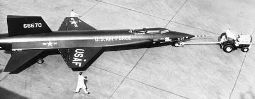
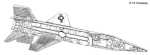
The X-15 is mainly a cylindrical fuselage, 49 feet 2 inches long. "Wing root" fairings begin just aft of the cockpit and extend nearly the entire length of the fuselage on each side. From these protrude stubby wings spanning 22 feet 4 inches and horizontal stabilizers. Vertical stabilizers stand both above and below the fuselage (dorsal and ventral), giving the aircraft a total height of 13 feet 1 inch.
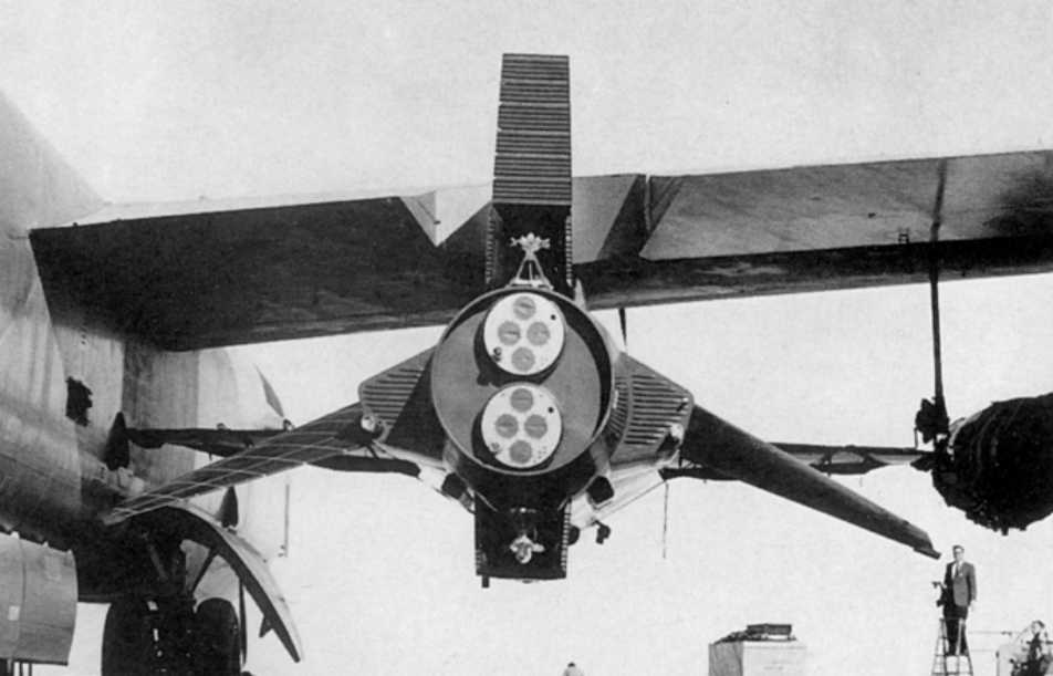
Let's start a walk-around at the aft end.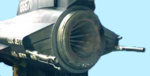 You're immediately looking into the business end of the XLR-99 rocket
engine, which consumes up to 15,000 pounds of anhydrous ammonia and
liquid oxygen in about 80 seconds on a typical flight. The engine's
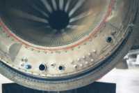
main chamber is made of CAREFULLY shaped and welded tubing that
circulates ammonia before it's burned. This preheats the fuel and cools
the engine that otherwise
would fry in its exhaust.
You're immediately looking into the business end of the XLR-99 rocket
engine, which consumes up to 15,000 pounds of anhydrous ammonia and
liquid oxygen in about 80 seconds on a typical flight. The engine's
main chamber is made of CAREFULLY shaped and welded tubing that
circulates ammonia before it's burned. This preheats the fuel and cools
the engine that otherwise
would fry in its exhaust.
 |
 |
 |
If you use your XRAY eyes to peer past the LOX jettison in the left fairing you'll first see a small spherical tank holding helium at 3600 psi. This particular helium purges explosive gases from the engine compartment, preferably before they ignite. Behind that is the end of a Godzilla-sized piece of plumbing that carries LOX from its tank to the engine compartment. The right fairing looks about the same, but the plumbing there carries ammonia.
Lurking behind the XLR-99 is the turbopump and a maze of assorted devices and plumbing. One of the devices is a gas generator, which is the X-15's breed of catalytic converter. When you feed 90% hydrogen peroxide into it, the H2O2 decomposes into superheated steam and oxygen on its catalyst beds. The resulting gases drive the centrifugal turbine in the turbopump, which then drives separate compressors for the ammonia and LOX.
Back on the outside, the stabilators (horizontal stabilizers also used as control surfaces) are the simplest pieces. They have 15
degrees anhedral, or cathedral, if you prefer. They swivel together for
pitch control, and move differentially for roll control, since the
wings have no ailerons. These, as well as the "rudders", have opposed
sets of irreversible hydraulic actuators -- you can make them push, but
they won't push back, so
you won't feel any air loads on the stick. Cockpit controls make up for
this
with a system of spring bungees to provide "natural" feel and pitch
trim.
also used as control surfaces) are the simplest pieces. They have 15
degrees anhedral, or cathedral, if you prefer. They swivel together for
pitch control, and move differentially for roll control, since the
wings have no ailerons. These, as well as the "rudders", have opposed
sets of irreversible hydraulic actuators -- you can make them push, but
they won't push back, so
you won't feel any air loads on the stick. Cockpit controls make up for
this
with a system of spring bungees to provide "natural" feel and pitch
trim.
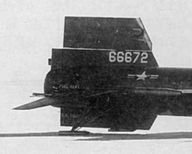
The vertical stabilizers get more complicated. Their triangular
cross
section provides some hypersonic stability and adequate room for
several
hydraulic actuators. Both dorsal and ventral fins are split  longitudinally into a fixed
part and a movable part. Panels on the aft third of the fixed (inboard)
sections spread apart to serve as speed brakes. It's best not to use
them if you're slow (like subsonic), because the only way to close the
speed brakes is to let a fairly heavy air load blow them back.
longitudinally into a fixed
part and a movable part. Panels on the aft third of the fixed (inboard)
sections spread apart to serve as speed brakes. It's best not to use
them if you're slow (like subsonic), because the only way to close the
speed brakes is to let a fairly heavy air load blow them back.
The top of the dorsal fin and the bottom of the ventral fin rotate to act as a rudder. The ventral piece extends below the landing gear, so it has four explosive bolts and an initiator (an explosive-driven piston) to jettison it before landing. Just remember not to jettison the ventral above 300 knots or mach 3.5, whichever is lower.
The main landing gear are skids that are locked against the aft fuselage until you're ready to release them. At that time they drop into place and lock, thanks to gravity and air loads. Since they don't have wheels, you don't have brakes. They're also so simple and reliable (right?) that they also lack any device to tell you, the pilot, whether they're up or down.
The wings have no dihedral, but they do have flaps and rockets. The rockets, two per wing, are thrusters to supply roll control out where there's little if any air. Like the turbopump's gas generator, they're powered by hydrogen peroxide.
Almost all of the fuselage's spare volume is split between the liquid oxygen tank in the forward end and the ammonia tank in the aft end. Each is divided into three interconnected chambers and a concentric cylindrical core. The LOX tank's core holds helium for pressurizing the peripheral ends of the two propellant tanks. Propellant feeds out through overgrown sewer pipes at the tank ends nearest the center of gravity.
Cutaway views, click
individually for a large image:
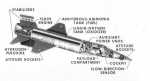
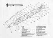
Other tanks for hydrogen peroxide, helium, and liquid nitrogen are crammed into the fuselage at either end of the main propellant tanks and between them. The compartment between the LOX tank and the cockpit also houses two APU's (auxilliary power units), each geared to an alternator and a hydraulic pump. The APU's are also turbines powered by hydrogen peroxide from their own gas generators.
One token sample of this plumber's nightmare (or is it plumber's heaven?) is what the nitrogen supply does. It cools the No. 2 electronics compartment, the alternators, the APU upper turbine bearings, the stable platform (for inertial guidance), and the ball nose. It purges the hydraulic reservoirs and inflates canopy and electronics compartment pressure seals. And it does some more things mentioned when we inspect the cockpit. And that's simple compared to the helium systems!
Walking forward again, we'll pass the cockpit for now. Next comes
the
nose gear, the proud possessor of two wheels. Of course it isn't
steerable,
it just castors -- who needs to steer anyway with so many 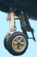 miles of dry lake for the landing rollout.
Like the skids, it drops by gravity and air loads, but there's a catch:
At a positive AOA the nose gear door
would have an air load trying to keep it closed, so it gets help.
Another
initiator gives it a boost, and a small air scoop opens down from it to
get
the airstream to hold it open.
miles of dry lake for the landing rollout.
Like the skids, it drops by gravity and air loads, but there's a catch:
At a positive AOA the nose gear door
would have an air load trying to keep it closed, so it gets help.
Another
initiator gives it a boost, and a small air scoop opens down from it to
get
the airstream to hold it open.
Up at the nose, eight rocket nozzles supply yaw and pitch control
for
the ballistic control system. All the 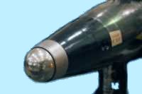 way forward is the q-ball -- a ball nose that measures dynamic pressure
("q" in aerodynamic equations) while swiveling around two axes to
measure
angle of attack and sideslip. These angles are worth knowing both at
reentry
and at low speeds, where the X-15 is least stable. However, before
reentry
it's up to inertial instruments fed by gyroscopes and accelerometers to
tell
you which way you're pointed and which way you're actually going.
way forward is the q-ball -- a ball nose that measures dynamic pressure
("q" in aerodynamic equations) while swiveling around two axes to
measure
angle of attack and sideslip. These angles are worth knowing both at
reentry
and at low speeds, where the X-15 is least stable. However, before
reentry
it's up to inertial instruments fed by gyroscopes and accelerometers to
tell
you which way you're pointed and which way you're actually going.
This pilot report is split into these four parts:
1. X-15 General
Description & Walkaround
2. X-15 Cockpit Check
3. X-15
Flight:
Heading Out to Launch
4. X-15
Flight:
Flying the Mission and Returning
Related to all four sections:
Photo credits
and pointers to related resources